
Heat Recovery from Kitchen Refrigeration
Energy Innovators Initiative
Cover of Publication Download PDF
(PDF, 317 KB)
Figure 1 - Refrigeration Compressor
Description
Commercial kitchens require walk-in refrigerators and freezers to store perishable food. Each unit is normally equipped with its own compressor/condenser package, which is cooled to remove the heat generated by the vapour compression refrigeration cycle. Typically, this heat is released into the environment. Where the equipment is water-cooled, that heat can be recaptured for useful purposes like domestic water heating.
Heat recovery systems are custom applications that must be sized for each particular situation. They use readily available plumbing and heating components. This fact sheet looks at the relevant issues when considering such a heat recovery system. The picture in Figure 1 shows a refrigeration compressor.
Technical Specifications
The heat recovery system consists of four components: a heat exchanger, pumps, heat sources and sinks, and controls. Figure 2 shows the system schematic and control sequences for an actual installation.
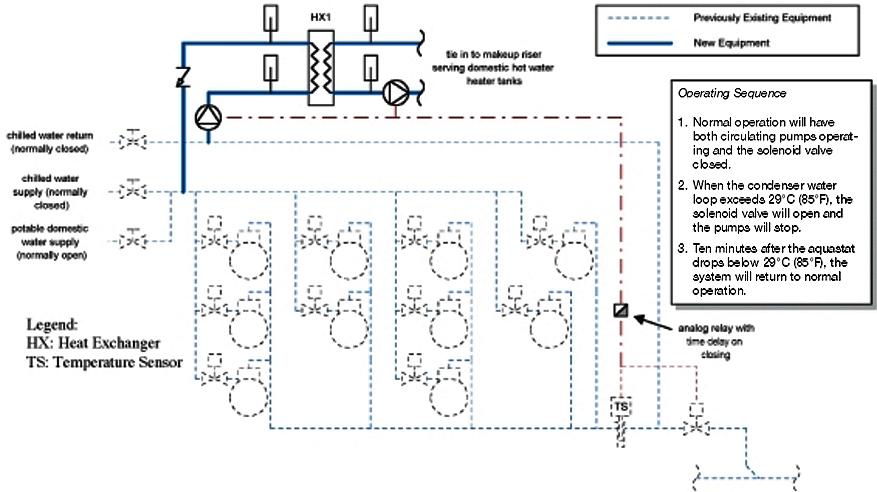
Figure 2 - Schematic of Heat Recovery Installation
Heat Exchanger – The main component of the system is the heat exchanger, which allows the warm medium (the condenser cooling water) to transfer heat to the cool medium (domestic make-up water). Brazed-plate heat exchangers are the most cost-effective models available, and are also very compact for retrofits. To minimize pumping requirements, select a low-pressure-drop heat exchanger.
Pumps – At least one new pump will be needed. Standard commercial circulators are appropriate, but they must be properly sized for the application. If they are too small, they will not deliver the appropriate flows through the condensers and heat exchanger. If they are too large, they will use excessive electrical energy and the system will be less efficient.
Sources and Sinks – For simplicity, the refrigeration condensers should be located close to one another, so that the heated water can be made available at a single point. The sink, where the heat is needed, should be easily accessible to the heat source through piping. Engineering estimates are required when planning the system to determine the quantity and daily availability of the rejected heat, the ability of the sink to accept the heat when it is available, and the value of the recoverable portion of the heat.
Safety Controls – The system must be designed to ensure that the refrigeration equipment is always operating within the manufacturer's recommended temperature range. Simple thermostatic control is used to reject excess heat to the environment when the heat sink is unable to accept it.
Energy Information
Heat recovered from the condenser of a water-cooled refrigeration system is proportional to the flow rate and the difference in temperature between the inlet and outlet of the heat exchanger.
Q = Flow × dT × (Unit Conversion Constant)
The vendor's selection software chooses the right size of heat exchanger for the application. A larger unit recovers more heat but is more expensive. Units are normally selected based on price, pumping requirements and heat recovered, for the lowest possible life cycle cost for the project.
The best payback will occur where there is a large temperature difference between the source and the sink, and where the sink is able to accept all of the heat generated at the source any time it is available.
Comparison
Installing a system to recover heat from refrigeration equipment is a straightforward engineering application, and should be considered for any water-cooled refrigeration system. Heat recovery can save in the following ways:
-
Fuel savings for domestic water heating;
-
Avoided cost of mechanical water cooling in closed systems; and
-
Reduced water consumption compared with the once-through water-cooled systems.
Case Study
In 1995, Homewood Health Centre in Guelph, Ontario, undertook a major energy management retrofit program. As part of the program, a system was installed to recover heat from 10 rack-mounted water-cooled kitchen refrigeration compressors. The existing system used domestic cold water to remove compression heat, with the used cooling water discharging to the drain. A brazed-plate heat exchanger was installed to recycle cooling water and preheat incoming domestic water from 10°C to 30°C. With the new system, less water is discharged to the drain and the domestic water heater tanks use less natural gas. The project saves $4,090 annually with a payback period of 2.3 years (Table 1).
| Input Data | |
|---|---|
| Case Study Natural Gas Rate | $0.17/m³ |
| Electrical Demand Rate | $5.10/kW |
| Electrical Consumption Rate | $0.054/kWh |
| Payback Summary | |
| Annual Natural Gas Savings | 10 009 m³ |
| Annual Water/Sewage Savings | 8953 m³ |
| Annual Electrical Consumption Increase | 10 452 kWh |
| Annual Electrical Demand Increase | 1.2 kW |
| Net Annual Cost Savings | $4,090 |
| Construction Cost | $9,400 |
| Payback Period (years) | 2.3 |
| Return on Investment | 43% |
For more information:
View other EII publications. To order paper copies, or for a faster response to inquiries, please contact EII
Energy Innovators Initiative
Office of Energy Efficiency
Natural Resources Canada
580 Booth St., 18th floor
Ottawa ON K1A 0E4
Tel.: (877) 360-5500
Fax: (613) 947-4121
Web site
Page details
- Date modified: