
Motor Controls
There are four major motor control topics:
- Protection
- Starting
- Stopping
- Speed Control
a. Motor Protection
Motor protection safeguards the motor, the supply system and personnel from various upset conditions of the driven load, the supply system or the motor itself.
Disconnect
A suitable disconnect device of sufficient capacity is required usually within sight of the motor, in accordance with Canadian Electric Code requirements. The purpose is to open the supply conductors to the motor, allowing personnel to work safely on the installation.
Overcurrent
Overcurrent protection interrupts the electrical supply in the event that there is excessive current demand on the supply system. Usually in the form of fuses or circuit breakers, these devices operate when a short circuit or a very heavy overload occurs.
Should the overcurrent protection for a motor trip, there is usually a good reason. Investigate repeated tripping thoroughly and avoid increasing the trip setting level until it can be confirmed the motor can safely tolerate a higher setting. Operating currents should be measured on all 3 phases to ensure the phases are balanced and the motor is not running constantly in an overloaded condition.
Overload
Overload protection safeguards the motor from mechanical overload conditions.
Four common overload protection devices are:
- Overload relays
- Thermal overloads
- Electronic overload relays
- Fuses
Overload relays operate on the magnetic action of the load current flowing through a coil. When the load current becomes too high, a plunger is pulled up into the coil, interrupting the circuit. The tripping current is adjusted by altering the initial position of the plunger with respect to the coil.
A thermal overload relay uses a heater connected in series with the motor supply. The amount of heat produced increases with supply current. If an overload occurs, the heat produced causes a set of contacts to open, interrupting the circuit. The tripping current is changed by installing a different heater for the required trip point. This type of protection is very effective because the heater closely approximates the actual heating within the windings of the motor, and has a "memory" to prevent immediate reset and restarting.
With electronic overloads, the load current is sensed and the heating effect on the motor is computed. If an overload condition exists, the sensing circuit interrupts the power circuit. The tripping current can be adjusted to suit the particular application. Electronic overloads often perform additional protective functions, such as ground fault and phase loss protection.
Fuses can also be used to protect a motor, provided some form of single phasing protection is also used to prevent motor operation if only one fuse blows.
Other Protection
Low voltage protection operates when the supply voltage drops below a set value. The motor must be restarted upon resumption of normal supply voltage.
Low voltage release interrupts the circuit when the supply voltage drops below a set value, and re-establishes the circuit when the supply voltage returns to normal. Phase failure protection interrupts the power in all phases of a 3-phase circuit upon failure of any one phase. Normal fusing and overload protection may not adequately protect a 3-phase motor from damaging single phase operation. This is particularly a critical issue for motors supplied by a delta configuration voltage. Without this protection, the motor will continue to operate if one phase is lost. Large negative sequence currents are developed in the rotor circuit, causing excessive current and heating in the stator windings which will eventually burn out. Phase failure protection is the only effective way to protect a motor properly from single phasing.
Phase reversal protection operates upon detection of a phase reversal in a 3-phase circuit. This type of protection is used in applications such as elevators where it would be damaging or dangerous to have the motor run in reverse.
Ground fault protection operates when one phase of a motor shorts to ground, thus preventing high currents from damaging the stator windings and the iron core.
Other motor protection devices include bearing and winding temperature monitors, current differential relays, and vibration monitoring.
Generally, the level of protection used will rise in proportion with the value of the motor. Therefore, motors less than 20 HP will not normally have anything more than overload and overcurrent protection, unless the motor is driving a critical process.
b. Motor Starting
Induction motor starters must supply the motor with sufficient current to provide adequate starting torque under worst case line voltage and load conditions.
3-Phase Motor Starters
Across the Line Starting of Induction Motors:
An across the line starter is the least expensive option and is usually used for induction motors (Figure 8-1). All NEMA design induction motors up to 200 HP, and many larger ones, can withstand full induction starts.
Manual starters are often used for smaller motors – up to about 10 HP. They consist of a switch with one set of contacts for each phase and a thermal overload device. The starter contacts remain closed if the power is removed from the circuit and the motor restarts when power is reapplied.
If there is a chance of injury from a motor restarting unexpectedly, a magnetic starter should be used instead.
Figure 8-1: Manual Starter
Magnetic starters are used with larger motors or where remote control is desired (Figure 8-2). The main element of the starter is the contactor, which is a set of contacts operated by an electromagnetic coil. Energizing the coil causes the contacts A to close, allowing large currents to be initiated and interrupted by a control signal. The control voltage doesn’t need to be the same as the motor supply voltage, and is often low voltage, allowing the start and stop controls to be located away from the power circuit.
A fuse protected step-down transformer is often used for higher voltage motors. In addition to start and stop functions, the low voltage supply can also power remote status lights, etc.
Figure 8-2: Magnetic Starter
Closing the starter button contacts energizes the contactor coil. An auxiliary contact B on the contactor is wired to seal in the coil circuit. The contactor de-energizes if the control circuit is interrupted by operating the stop button, having the thermal overload relay operate, or if power is lost.
The overload contacts are arranged so an overload trip on any phase will cause all phases to open.
Contactors are rated for various operating voltages and are sized according to motor HP and type of duty expected.
Installing an extra Emergency RED STOP button next to a motor (or remotely) makes good sense when choosing a magnetic starter. The normally closed stop buttons are wired in series in the stop circuit such that depressing any one of them de-energizes the magnetic contactor.
Reduced Voltage Starters:
If the driven load or the power distribution system cannot accept a full voltage start, some type of reduced voltage or "soft" starting scheme must be used. Reduced voltage starters do not save energy. They are simply intended to address starting issues such as voltage sag and mechanical protection, and can only be used where low starting torque is acceptable. (See also Power Factor Controller).
Primary Resistance Starters:
Closing the contacts at A connects the motor to the supply via resistors which provide a voltage drop, thus reducing the starting voltage available to the motor (Figure 8-3). The resistors’ value is chosen to provide adequate starting torque while minimizing starting current. Motor inrush current declines during acceleration, reducing the voltage drop across the resistors and providing more motor torque. This results in smooth acceleration.
Figure 8-3: Primary Resistance Starter
Autotransformer Starters:
An autotransformer is a single winding transformer on a laminated core, with taps at various points on the winding (Figure 8-4). The taps are usually expressed as a percentage of the total number of turns and thus percentage of applied voltage output.
Three autotransformers are connected in a wye configuration or two in an open delta configuration, with taps selected to provide adequate starting current.
The motor is first energized at a reduced voltage by closing contacts A.
Figure 8-4: Autotransformer Starter
After a short time, the autotransformers are switched out of the circuit by opening contacts A and closing contacts B, thus applying full voltage to the motor. The autotransformers need not have high capacity as they are only used for a very short period of time.
Solid State Starters:
Solid state starters use thyristors or other solid state devices (e.g. silicon controlled rectifier, triacs, transistors, etc.) to control the voltage applied to the motor. A thyristor is essentially an electronic switch that can replace a mechanical contactor. However, unlike a mechanical contactor, a thyristor can be turned on and off at a point on the AC waveform during each cycle. For a 60-cycle AC, this can be 120 times per second per phase (i.e. on-off cycle per half cycle). Reducing the ON time during each cycle has the effect of reducing the average voltage output to the motor. By gradually increasing the ON time, the voltage increases gradually to full voltage. By reducing the voltage on start, current is also reduced. Start-up time tends to be longer as a result compared to a line voltage start. The starting function does not save energy, but rather addresses starting issues including voltage sag and mechanical protection.
Since the thyristors can be precisely controlled, it is possible (depending on the features of the individual starter) to limit starting current and also provide soft stopping (very useful for loads such as parts conveyors to prevent relative shifting on the belt).
Starting current and torque are easily adjusted and solid state starters often include other functions such as overload protection. See also Power Factor Controller.
Figure 8-5: Solid State Starter (Simplified)
Light dimmers use thyristors to dim lights. Turning the knob or moving the slider changes the portion of time the thyristor is turned on during each ½ cycle. Full brightness is achieved when the thyristor is turned on at the start of each ½ cycle.
Wye-Delta Starting:
Wye-delta starting (Figure 8-6) can be used with motors where all six leads of the stator windings are available (on some motors only three leads are accessible).
Figure 8-6: Wye-Delta Starter
By first closing contacts A and B, the windings are connected in a wye configuration which presents only 57% of rated voltage to the motor.
Full voltage is then applied by reconnecting the motor in a delta configuration by closing contacts C and opening those at A.
The starting current and torque are 33% of their full voltage ratings, limiting applications to loads requiring very low starting torque.
This type of starter is physically large and costly as many contactors are required to perform this task. Loads such as large chillers may employ a wye-delta starter. Solid state starters are becoming less costly and are competing with this special motor/starter arrangement.
Variable Frequency Drive Starting:
Variable Frequency Drives (VFDs) are also an effective means of starting a motor. By accelerating the motor up to speed by ramping the frequency of the voltage applied to the motor, inrush current can be minimized while maintaining sufficient torque to drive the load. This application of VFDs does not save energy; however variable torque applications do.
Power Factor Controller:
A power factor controller (PFC) is a solid state device which reduces voltage to the motor when the motor is lightly loaded. The magnetizing current and resistive losses are reduced in proportion to this reduction in voltage. When the load increases, the voltage rises to normal. The reduction in voltage results in improved power factor during these low load periods.
PFCs have been produced for single and 3-phase induction motors. To save energy, the average motor load needs to be minimal for extended periods of operating time. Constant load devices such as compressors are not good candidates for PFCs if the motor has been optimally sized for the load. A table saw motor would be a potential application if the motor is operated for extended periods and the material throughput is not constant. PFCs can also provide soft starting and stopping functions.
Originally developed by NASA in 1984, variations of PFC’s have been marketed for several years. Many have been promoted to the consumer market as energy saving receptacles. While the basic concept is sound, the plugs will do little to save energy in modern appliances that have been mandated to be energy efficient. Older appliances such as refrigerators may provide modest energy savings using these devices.
Part Winding Starters:
Part winding starters are sometimes used on motors wound for dual voltage operation such as a 230/460 V motor. These motors have two sets of windings which are connected in parallel for low voltage, and in series for high voltage operation.
When used on the lower voltage, the motors can be started by first energizing only one winding. This limits the starting current and torque to approximately one half of the full voltage values. The second winding is then connected normally once the motor nears operating speed.
Single Phase Motor Starters
Single phase motors are typically under 10 HP. Starters range from a simple dry contact switch for small single phase motors to magnetic contactors for larger sizes.
Solid state starters can be used for soft start motors to limit inrush current as well as provide variable speed capability. This type of starter is particularly suited to farm applications as it permits the use of larger motors on constrained single phase lines.
As noted previously, magnetic starters are always recommended if safety is a concern. A simple switch may cost only a few dollars, whereas a magnetic starter may cost $100 or more; however, avoiding a serious injury can make the magnetic starter priceless.
DC Motor Starters
Because the DC resistance of most motor armatures is low (0.05 to 0.5 ohms), and because the counter EMF does not exist until the armature begins to turn, it is necessary to use an external starting resistance in series with the armature of a DC motor to keep the initial armature current to a safe value. As the armature begins to turn, counter EMF increases. Because the counter EMF opposes the applied voltage, the armature current is reduced.
As the motor comes up to normal speed and full voltage is applied across the armature, the external resistance in series with the armature is decreased or eliminated. Controlling the starting resistance in a DC motor is accomplished either manually, by an operator, or by any of several automatic devices. The automatic devices are usually just switches controlled by motor speed sensors (Figure 8-7).
Another means of starting DC motors is via electronic reduced voltage starters which reduce inrush currents. This type of control is especially popular where variable speed control is required.
The DC motor is reversed by reversing the direction of the current in the armature. As the armature current is reversed, the current through the interpole is also reversed. Therefore, the interpole retains the proper polarity to provide automatic commutation.
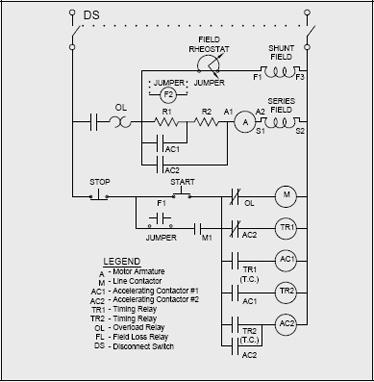
Figure 8-7: Example of a DC Motor Starter
c. Motor Stopping
The most common method of stopping a motor is to remove the supply voltage and allow the motor and load to come to a stop. In some applications however, the motor must be stopped more quickly or held in position by some sort of braking device.
Electrical Braking
Electrical braking uses the windings of the motor to produce a retarding torque. The kinetic energy of the rotor and the load is dissipated as heat in the rotor bars of the motor. Two means of electrical braking are plugging and dynamic breaking.
Plugging brings an induction motor to a very quick stop by connecting the motor for reverse rotation while it is running. To prevent the motor from reversing after it has come to a stop, the power is removed by means of a zero speed switch.
Dynamic braking is achieved by removing the AC power supply from the motor and applying direct current to one of the stator phases.
Neither plugging nor dynamic braking can hold the motor stationary after it has stopped.
Hand held circular and portable miter saws often employ electric braking. When the switch is released, the motor stops the spinning blade faster than if it were allowed to coast. If this feature stops working on a universal motor, check the brushes for wear and replace if necessary.
Regenerative Braking
Regenerative braking is a means of slowing a motor to a standstill by temporarily converting it to a generator when a stop command is issued. The motor (now generator) output is dissipated through power resistors or applied to charge a battery.
Regenerative braking is used in hybrid electric vehicles. Some of the energy is dissipated by conventional brakes while a portion is returned to the vehicle battery. For vehicles, this arrangement is needed to give the driver better control over braking. Charge acceptance of the battery depends on its state of charge.
Mechanical Braking
Mechanical braking refers to devices external to the motor which provide retarding torque.
Most rely on friction in a drum or disc brake arrangement and are set with a spring and released by a solenoid or motor.
These devices have the ability to hold a motor stationary.
An eddy current brake is an electromechanical device that provides a retarding torque by inducing eddy currents in a drum via an electromagnetic rotor attached to the motor shaft. The amount of braking force can be controlled by altering the rotor current.
Eddy current brakes cannot hold the motor stationary.
d. Motor Speed Control
The following are examples of typical motor speed controls. (This topic is more thoroughly covered in the Adjustable Speed Drive Guidebook).
Speed control can be classified into five general areas:
- Multi-speed motors.
- Wound rotor induction motor control
- DC motor controllers
- Variable speed drives for induction and synchronous motors.
- Mechanical speed control
Multi-speed Motors
Induction motors with multiple speed windings are suitable for applications requiring up to four discrete speeds. Speed is selected by connecting the windings in different configurations and is essentially constant at each setting. These motors are often found in applications such as ventilating fans and pumps.
Typically multi-speed motors are not particularly efficient at reduced speed. This type of motor is therefore is a poor choice for driving fans at low speed for constant air flow applications. An ECM would be a better choice for variable speed fans.
Wound Rotor Motor Control
The torque-speed characteristics of a wound rotor induction motor can be altered over a wide range by adding external resistance to the rotor circuit via the slip rings. Power extracted from the rotor circuit is either wasted as heat or recovered and converted into useful electrical or mechanical energy.
Higher maintenance is required for wound rotor motors. Periodic cleaning and brush replacement is needed.
DC Motor Control
The DC motor is the simplest to control as speed is proportional to armature voltage. Speed can be varied over a very wide range.
The DC voltage can be converted from AC by phase controlled rectifiers or generated by a motor-generator set (Ward Leonard system).
Exercise treadmills typically used 90VDC motors whose speed is varied by a variable voltage dc controller.
Variable Frequency Drives (VFDs) for Induction and Synchronous Motors
Variable frequency drives (VFDs) are applied when there is a need to control speed (induction and synchronous) and eliminate slip (induction). The speed of induction motors can be adjusted by electrical and mechanical means. Variable frequency drives control motor speed electrically.
Using a VFD can improve overall energy efficiency in spite of the fact that the drive itself consumes energy. Applications where the load requirement varies over a wide range with significant part load operation make VFDs an attractive option. Overall energy savings are realized using VFDs compared to the alternative methods of varying output (e.g. fan dampers and pump recirculation).
VFD’s operate by varying the frequency of the AC voltage supplied to the motor using solid state devices. The voltage is also controlled to provide a constant voltage to frequency ratio. These have become the preferred way to achieve variable speed operation as they are relatively inexpensive and very reliable.
The ability of a motor to cool itself effectively is reduced as the motor is slowed down.
Oversizing the motor or providing integrated forced air ventilation may be required with extended operation at low speeds and high loads.
Operation at different speeds can cause mechanical resonances in driven equipment. These speeds should be identified and programmed out of the VFDs operating range.
VFDs generate harmonic voltages and currents which can, in some cases, cause undesirable effects on the electrical distribution system and affect equipment operation. Sometimes isolating transformers, line reactors or filtering devices will be required to minimize these effects. Some new generation VFDs eliminate harmonics internally and eliminate external mitigation requirements.
The following graph of the allowable torque of NEMA design A&B motors due to reduced cooling by operation at reduced speeds can be used as a guide for derating motors or selecting an appropriately oversized motor (Figure 8-8).
VFDs have become cheaper and more reliable in recent years. That said, one should first assess if a VFD is needed or if a simpler solution is available. One should assess how much of the time the motor will be partly loaded to determine if significant savings are achievable or not. Unless the VFD is bypassed when the motor is operated at or near full load, the VFD will consume 2% to 5% of the total load rating and could cost more to operate than a fixed speed motor.
Figure 8-8: The Effect of Reduced Cooling on Torque Capability
Application of a VFD can cause voltage transients well above the rated voltage of the motor and can lead to failure of the insulation system. This is due to interactions of the PWM switching frequency and wave shape, the cable length supplying the motor, and the inductance of the motor.
Increased stress on motor insulation can occur because of voltage spikes. The high-frequency interruption from a VFD can produce very high voltage spikes which can rapidly break down conventional motor insulation.
This problem can be minimized by using appropriate filtering (line reactors), keeping cable runs short (<100 feet), using inverter duty motors with improved insulating systems, and ensuring that repaired motors have upgraded insulation systems.
Mechanical Speed Control
The speed at which the load is driven can also be adjusted by using devices external to the motor. Examples include continuously variable transmission, fluid coupling, eddy current clutches and the magnetic coupling drive. These devices convert the rated speed of the motor to the required load speed.
The magnetic coupling drive can use electromagnets or more recent developments employing rare earth magnets [e.g. neodymium/iron/boron (Ne/Fe/B)] to transmit torque between motor and load. A magnetic coupling can allow a motor to start up unloaded and gradually apply torque.
Mechanical speed control devices have internal losses, but these losses are usually fewer than when other means of control such as pump throttling or fan baffling are used. Energy savings for part load centrifugal loads can be 30% or more compared with mechanical throttling methods (Ref. 15). The latter statement also applies to VFDs.
Previous: Motor Selection | Table of Contents | Next: Maintenance
Page details
- Date modified: