
5. Generic Processes and Auxiliary Systems Descriptions
The purpose of highlighting commonly used generic processes is to pinpoint where opportunities may exist to minimize resource consumption and to reduce process discharges. Illustrations of generic processes together with process descriptions are provided in this guide. The process diagrams identify resource inputs and sources of effluents. Both the descriptions and diagrams are highly simplified and are intended to introduce the technology to readers who are unfamiliar with the industry.
Several of the processes described below may also be enhanced by feeding more than one material type, colour or grade into the process to manufacture products with layers of dissimilar materials. This enables the manufacturer to obtain improved technical-, aestheticor cost-benefits from a single process. In addition, robotics play an increasingly important role in enhancing repeatability in processes, as well as in reducing cost and the risk of accidents. To keep things simple, enhancements such as these are ignored throughout the process descriptions outlined in the text.
Illustrations of auxiliary systems are also provided. Examples of some of the systems illustrated include a closed-loop free-cooling water system, a compressed-air system and a pneumatic raw-material handling system. Resource consumption areas and emission points are pinpointed in each of the generic auxiliary systems described.
Readers already familiar with generic processes, process technology and auxiliary systems may proceed directly to Chapter 6, "Generic Improvement Opportunities."
5.1 Profile Extrusion
Single screw extrusion is the most commonly used technology for profile extrusion. A thermoplastic raw material, typically in pellet form, is fed from a hopper into a barrel that houses a rotating screw. A small laboratory-sized extruder may have a screw diameter of 10 mm, while screws for high-volume extruders may have diameters in excess of 300 mm. The screw is typically driven by a variable speed electric motor that may be coupled to a single- or multi-speed gear box.
The screw system performs several functions:
- It conveys material from the hopper to a die located at the opposite end of the barrel.
- The screw plasticizes and pressurizes the material. Heat is generated by a combination of internal heating due to shear and heater bands located outside the barrel. The barrel may be vented to allow gases and water vapour to escape. Venting requires a multiplestage screw, with a decompression zone between the compression stages.
- The screw may be used to blend in colorants and other additives.
- The control of melt temperature, homogeneity and pressure are all critical factors. Thermocouples are used to sense temperature along the barrel and to control the amperage to the heater bands. To prevent excessive shear heat from degrading the material, some barrel zones may be water- or air-cooled.
The plasticized material is forced through a die to form the desired shape. After passing through the die, the partially solidified extrudate may be further formed by callipers or vacuum sizers to achieve the final desired configuration and to maintain required tolerances. The extrudate is then water- or air-cooled. When the material has solidified sufficiently to resist damage from handling, a puller system is used to maintain a constant tension on the extrudate. Beyond the puller, a travelling saw or shearing mechanism is used to cut the product into desired lengths for shipment or further processing.
Twin extruders, with two parallel screws, are capable of high output with low shear and are typically used for large volume processing of heat-sensitive materials. Typical applications include siding and pipe produced from non-pelletized (powder) materials. Co-extrusion – the use of more than one extruder to feed a single die – is common.
Most custom operations use various sizes of general purpose extruders. However, significant productivity, quality and energy efficiencies may be achieved by using a machine matched to a specific job. For a specific material and throughput, it is important to select the appropriate screw diameter, length to diameter ratio and operating conditions.
A wide variety of thermoplastic materials may be processed by extrusion. The largest volume material is PVC (polyvinyl chloride), which is used for construction vinyl siding, sewer pipe and along windows (or lineals). ABS (acrylonitrile butadiene styrene) is used for refrigerator trim, drain pipes and furniture components.
Resource Consumption and Emissions in the Profile-Extrusion Process
The major energy requirement for this process is the electricity to drive the extruder-screw motor. Some electrical energy is used to drive puller motors and cut-off saws. In other cases, the cut-off equipment may be operated by compressed air.
Significant amounts of water may be used to cool the lineals. This water is often recirculated.
Water vapour and other gaseous emissions are released into the atmosphere from barrel vents, the feeder throat and the nozzle.
Figure 5-1 Resource Consumption and Emission Points in the Profile Extrusion Process.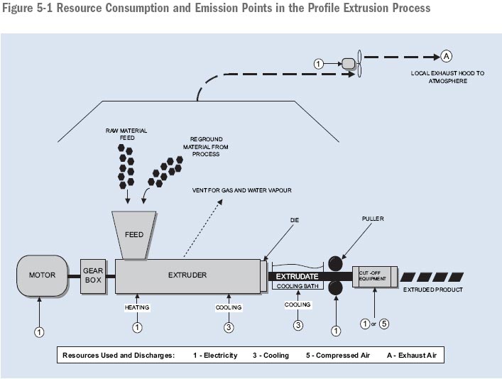
5.2 Thermoplastic Injection Moulding
Thermoplastic injection moulding is a versatile process used to produce a wide variety of end products. With proper tool design and material selection, injection moulded parts can provide a broad range of physical properties, decorative features and resistance to chemical attack and ageing. When required, metal inserts may be used in injection moulded parts to provide additional strength.
Injection moulding machines are commonly classified by clamp tonnage – the force required to resist the pressure exerted by the material injected into the mould during the injection process. The pressures are frequently high, 20,000–30,000 psi. As a result, clamp tonnages normally range from 20 tonnes for a small machine to 6,000 tonnes or more for a large press.
The plasticizing of the material is similar to the process described under the profile-extrusion process description. The major difference is that in the injection-moulding process, the screw retracts while it is rotating and a pre-determined amount of plasticized material accumulates in front of the screw. The screw stops rotating at this point, and the screw assembly moves forward to force the material through a nozzle into a mould under high pressure.
Cycle times vary with materials used, wall thickness of the parts and tool technology. Thin-walled containers typically have a cycle time of a few seconds. Large parts with heavy sections will take several minutes to solidify before being removed from the mould.
For parts that require trimming, 100 percent inspection or secondary operations, an operator manually removes the parts from the mould. Alternatively, the parts may be allowed to fall into a container, or robots (sprue pickers) may be used to remove the sprues and/or parts from the mould. In more sophisticated applications, robots are used to package the parts or to transfer them to a secondary operations station.
Various options exist for feeding the material into the mould cavities. The conventional method is to feed material through a sprue and a runner system into one or more mould cavities. After the part has solidified, the mould opens and the parts may be trimmed from the runner system. In most applications, the sprues and runners are reground and fed back into the process.
Various levels of sophistication in tool technology help reduce the labour and energy required to trim parts after moulding. For example, tunnel or submarine gates are used to separate the part from the runner system during the mould-opening sequence.
The effort to separate and re-grind runners may be totally eliminated by using a hot-runner system. Heaters built into the mould keep material in the runners in a molten state until the next shot. Although hot-runner tooling is more costly, the technology is commonly used for high-volume small parts, especially when heat-sensitive materials are used. With conventional tooling, the runner-to-part weight ratio is typically quite high, and materials may become degraded by passing through the heating cycle several times.
Injection moulding is used to process a broad range of materials. Commodity resins, such as polyethylene, are found in ice cream tubs and polystyrene is found in CD cases.
When the end-use requires physical or chemical properties that are not available in commodity grades, engineered plastics are used. Nylon, for example, is frequently used in applications that require toughness and lubricity. Some ABS parts, such as faucet handles and automotive trim, are electroplated for decorative and functional applications.
Resource Consumption and Emissions in the Injection-Moulding Process
The major energy requirement for this process is the electricity to power the hydraulic systems. The majority of the energy is used to plasticize the material, with lesser amounts required for injection and to transport the moulds.
The moulds are usually water-cooled. This water is typically recirculated.
Water vapour and other gaseous emissions are released into the atmosphere from barrel vents, the feeder throat and the nozzle. Mould releases, if used, will also contribute to air emissions. Mould cooling water is typically recirculated. Leaks from the hydraulic systems may contaminate plant wastewater.
Figure 5-2 Resource Consumption and Emission Points in the Injection-Moulding Process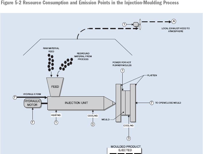
5.3 Flat Film or Sheet Extrusion
In this process, a slot die, often three to four metres wide, is mounted on an extruder to produce a film. This film is typically fed vertically into a cooling bath and is passed over chilled rolls. The highly polished rolls produce a smooth flat film surface that has excellent clarity. Film thickness is partially a function of the cooling rate. Accurate temperature control of the rolls and cooling baths is important.
The roll mechanism is run at a speed that stretches the film, while reducing its thickness. This process produces a film that has superior physical properties in the direction of the stretch and lower properties across the film. Biaxially oriented film with good strength in all directions may be obtained by stretching the extruded film both longitudinally and transversely.
Sheet may be produced with a wide range of thicknesses, from thin film for packaging applications to heavier gauges used by whirlpool tub manufacturers. Sheet may be co-extruded from more than one type of material and may be supplied with embossed surfaces.
A wide range of polymers may be processed by sheet extrusion; polyethylene, polypropylene and polystyrene are commonly used.
Resource Consumption and Emissions in the Flat-Film or Sheet-Extrusion Process
The major energy requirement for this process is the electricity to drive the extruder screw motor. Some electrical energy is used to drive rolls and winder motors. Significant amounts of water may be used for the chill rolls and cooling baths. This water is often recirculated. Water vapour and other gaseous emissions are released into the atmosphere from barrel vents, the feeder throat and the die area.
Figure 5-3 Resource Consumption and Emission Points in the Flat-Film or Sheet-Extrusion Process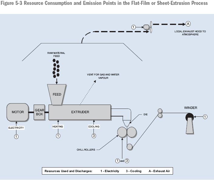
5.4 Blown-Film Extrusion
In this process, plasticized material is forced through a ring-shaped die. Die diameters may range from a few centimetres to over two metres. The technology required to distribute the melt evenly around the die and to attempt to produce uniform-film gauge thicknesses is complex.
The tube formed by the die is expanded into several times its original diameter by air pressure introduced through the die. Air blown from a ring outside the bubble, which may be several storeys high, is used to cool the material from the outside. Both the external and internal air streams may be chilled. Automatic air rings may be used to allow individually controlled air streams to be directed at specific areas of the bubble. Automatic measurements of film thickness are used to feed back information to control the velocity and/or the temperature of the individual air streams.
Once the material has solidified, the bubble is passed through a collapsing frame into pinch rolls. These rolls permit a constant pressure to be maintained inside the bubble by preventing the loss of air that is introduced through the die. The air pressure is used to control the size of the bubble and, consequently, the thickness of the blown film.
Products such as garbage bags are made from a single polymer. More complex products that require specific barrier properties, such as medical applications or food wraps, may be produced from as many as seven different materials co-extruded in a single process.
The blown film may be slit and wound on rolls as flat film. Alternatively, the film may undergo several additional processes in-line. It may be treated to improve adhesion for glues and inks, printed, gusseted, and cut into products such as grocery bags.
Throughputs in excess of 1,500 kilograms per hour have been achieved.
Polyethylene is the most commonly used polymer for high-volume blown-film extrusion applications.
Resource Consumption and Emissions in the Blown-Film Extrusion Process
The major energy requirement for this process is the electricity to drive the extruder screw motor. Significant energy is used to drive cooling fan motors and lesser amounts are required for winder equipment.
Water vapour and other gaseous emissions are released into the atmosphere from barrel vents, the feeder throat and the die area.
Figure 5-4 Resource Consumption and Emission Points in the Blown-Film Extrusion Process.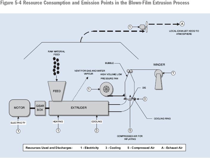
5.5 Blow Moulding
5.5.1 Extrusion Blow Moulding
In this process, a screw plasticizes material that is forced through a ring-shaped die to form a tube of material called a parison. For small parts, the extrusion of the parison may be continuous, in which case the maximum size of the part is limited by the tendency of the parison to stretch under its own weight. For larger parts, or more-difficult-to-process engineering materials, the melt is collected in an accumulator system and is injected intermittently by a plunger. Reciprocating screws, operating in the same manner as for injection moulding, may also be used to form a parison. To conform with product and process demands to have more or less material in specific areas of the part, moving mould components can be used to vary the thickness of the parison while it is being formed.
The parison of molten material is captured between mould halves. Air is injected into the parison to inflate the material into contact with the mould walls. After cooling, the part is ejected and trimmed of flash. Typically, multiple moulds are shuttled or rotated to allow cooling to take place while another mould is capturing the subsequent parison. Since the pressure exerted by the air, which is used to expand the parison, is relatively low, moulds can be made of aluminum. However, polished steel moulds are typically used for parts that require a good surface finish. Moulds may be either cooled or heated, depending on the materials used and the appearance requirements of the finished product.
5.5.2 Injection Blow Moulding
Large quantities of containers, such as bottles or jars, with a good surface finish and tight tolerances may be produced by injection blow moulding. This process typically uses a three-station indexing table. The first station is used to injection mould a preform. At the second station, the preform is introduced into another mould and is blown to form the finished product. The third station is used for parts removal.
Alternatively, a preform may be produced in a separate injection-moulding machine. For high volume applications, such as beverage containers, the injection mould may have over one hundred cavities. The preform is later re-heated and inserted into a blow-moulding machine. This process permits more complex shapes and a more economical use of raw materials.
Polyethylene, polystyrene and polyethylene terephthalate resins are commonly used materials for packaging applications and beverage containers.
Resource Consumption and Emissions in the Blow-Moulding Process
The major energy requirement for this process is the electricity to drive the extruder screw motor. Some electrical energy is used to drive mould-transport mechanisms, whether electrically or hydraulically operated, and to provide compressed air for blowing. In injection blow moulding, gas may be used to re-heat preforms. Cooling water, often recirculated, may be used for moulds.
Water vapour and other gaseous emissions are released into the atmosphere from barrel vents, the feeder throat and the nozzle. When gas is used for heating preforms, the combustion contributes to air emissions.
Figure 5-5 Resource Consumption and Emission Points in the Blow-Moulding Process.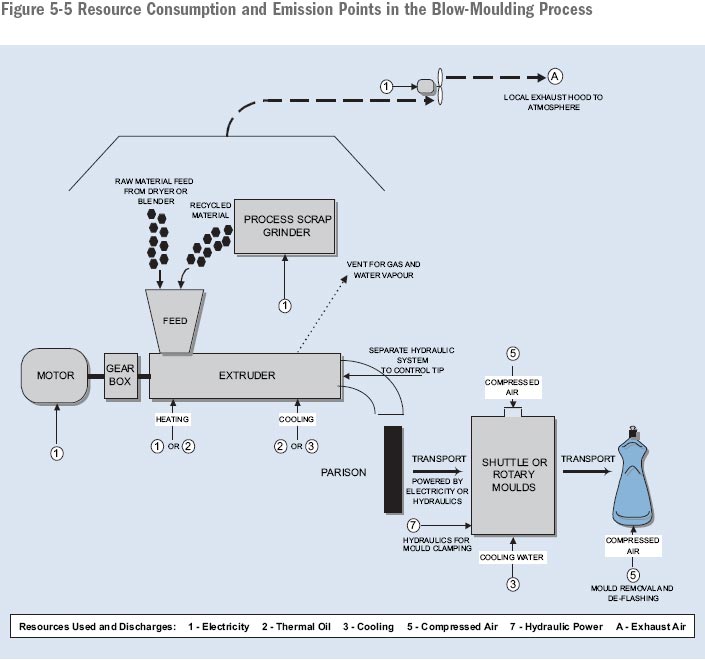
5.6 Compression Moulding of Thermoset Plastics
Thermoset plastics behave differently when heated. These materials undergo an irreversible chemical process when heated and cannot be re-plasticized. The five processes described earlier (sections 5.1–5.5) commonly use thermoplastic materials. These soften when heated and re-harden when cooled. For most thermoplastics, this melting and cooling process can be repeated a number of times without a significant loss of physical properties.
Thermoset raw materials are supplied in either granular form or as sheet moulding compounds, which are supplied in rolls of a putty-like sheet. Typically, sheet moulding compounds contain a proportion of glass fibres that impart improved physical properties to the end product.
In compression moulding, a pre-weighed amount of thermoset material is placed into a mould cavity. Some thermoset materials can be moulded at ambient temperatures. However, shorter cycle times are achieved by using heated moulds. The heated mould is closed under hydraulic pressure (often as high as 5,000 psi) and the material flows to fill the mould.
The clamping capacity of a large compression-moulding machine may exceed 10,000 tons.
The low cost, low weight and high strength of glass-filled compression-moulded products has led to an increased penetration of this technology into many mass transportation and automotive applications.
Thermosetting polyesters, typically with added glass fibre, are commonly used in compression-moulding applications.
Resource Consumption and Emissions in the Compression-Moulding Process
The major energy requirement for this process is the electricity to drive the hydraulic system for the press. Energy is also required to heat the moulds, either directly through resistance heating, by thermal oil or by steam. Emissions from the moulding compound are released into the air during the process. Oil leaks from the hydraulic systems may contaminate stormwater.
Figure 5-6 Resource Consumption and Emission Points in the Compression-Moulding Process.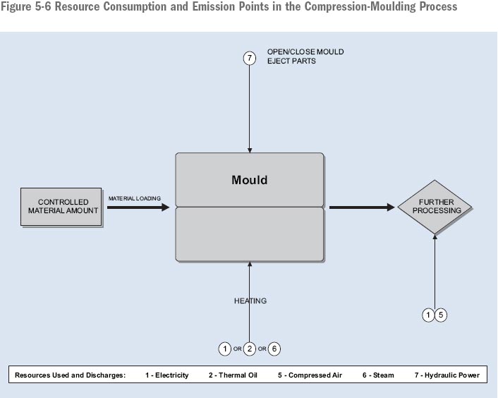
5.7 Foam Moulding
The foam-moulding process introduces a mixture of liquid raw materials into a mould. This mixture undergoes a chemical reaction and expands to fill the mould. For fast-reacting foams, closed moulds are used in a process called reaction injection moulding. Slower acting foams may be poured into open moulds, which are then closed while the foam expands to fill the mould.
To ensure consistency in the finished product, a precise control of the raw material mixing is necessary. Low-pressure mixing technology, used for filling open moulds, is capable of accurately metering and mixing 10 different ingredients with shot sizes ranging from a few grams to hundreds of kilograms.
For high-volume production, a single mixing head is used to fill a series of moulds that travel on a conveyor system while the foam cures. The moulds are opened at an unloading station and the finished parts are removed. For certain applications, inserts may be loaded into the mould.
A trimming operation is often required to remove unwanted flash from the parts.
The blowing agents and other chemical components may also be controlled to produce foams of various densities. Rigid foams are frequently used for insulation, while flexible foams are commonly found in furniture, car seats and energy-absorbing padding.
Polyurethanes are the most frequently used family of materials.
Resource Consumption and Emissions in the Foam-Moulding Process
The major energy requirement for this process is the electricity to drive the material-dispensing systems. Lesser amounts are required for mould transport and for hydraulic-mould operating systems, when used.
Most foam-moulding processes do not use cooling water. However, the use of solvents to clean dispensing equipment may generate liquid wastes that need special handling. Air emissions include releases from the curing material, solvents and mould releases. Solid waste from the trimmings and other scrap are often recycled in carpet underpadding.
Figure 5-7 Resource Consumption and Emission Points in the Foam-Moulding Process.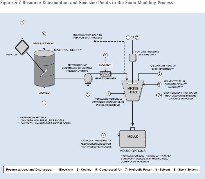
5.8 Auxiliary Systems
In addition to the primary processes described above, most plants also use several auxiliary systems such as those listed below.
Cooling Systems – Once Through and Closed Loop
Once-through cooling uses line water to remove heat from the equipment or process prior to discharging to the sewer system. Closed-loop cooling reuses the water by removing the heat that is absorbed from the process by circulating the water either through a chiller or a cooling tower.
Closed-Loop "Free" Cooling System
A free cooling system uses ambient outside air to reduce chiller-system energy requirements in cool weather.
Hydraulic Power Unit System
Hydraulic power units are composed of a hydraulic pump usually driven by an electric motor. The pump pressurizes hydraulic fluid, which in turn powers a variety of components such as hydraulic cylinders and hydraulic motors.
Thermal Oil Heater/Cooler Systems
Thermal oil heater/cooler systems consist of a tank filled with thermal oil, a pump and either a heater or cooling element. The thermal oil is used to control the temperature of the equipment or process.
Compressed-Air System
Compressed air is used for a variety of applications within a plant that includes powering cylinders, motors and actuators. The compressed-air system consists of a motor driving a compressor that compresses air into a receiver. From there, the air typically goes through a dryer before being distributed throughout the plant to various applications.
Pneumatic Raw Material Handling System
A pneumatic raw material handling system is used for the transfer of larger quantities of materials such as pellets within a plant. In addition to the pneumatic conveying system, depending on the type of material, a mixing or blending system and a dryer may be included in the system.
The above-mentioned processes are illustrated in Figures 5-8, 5-9, 5-10 and 5-11. Resource use and discharges are pinpointed in each of the auxiliary system illustrations.
Figure 5-8 Auxiliary Process - Once-Through and Closed-Loop Cooling Water Systems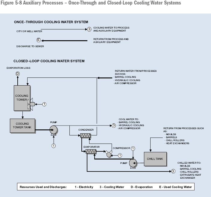
Figure 5-9 Auxiliary Processes - Closed-Loop "Free" Cooling Water System.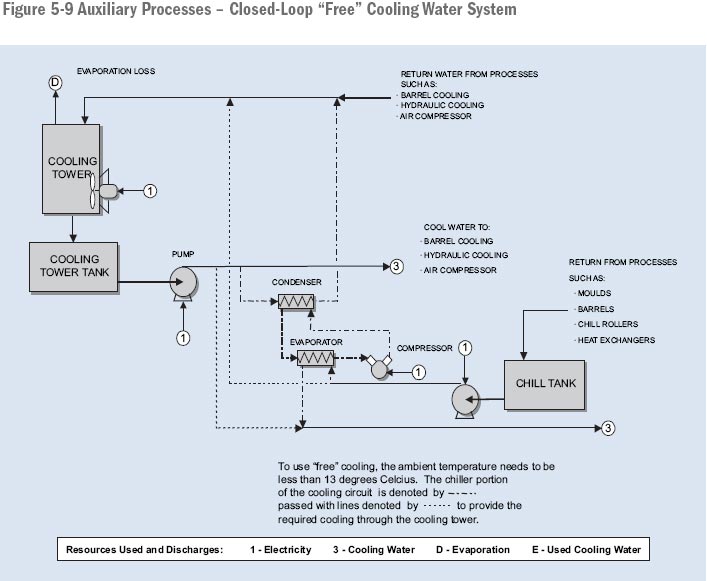
Figure 5-10 Auxiliary Processes - Hydraulic Power and Thermal Oil Systems.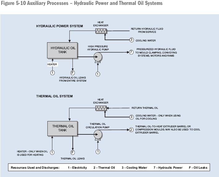
Figure 5-11 Auxiliary Processes - Compressed-Air and Pneumatic Material Handling Systems.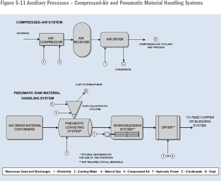
Page details
- Date modified: