
DC Motors
5 DC Motors
DC motors possess characteristics that make them attractive for certain applications. For example, very high torque at low speeds makes the series DC motor attractive for traction and engine starting applications.
Rotational speed can easily be controlled by varying the supply voltage.
The following is a general description typical of the DC motors:
The rotating part (rotor) of a DC motor is called the armature, and consists of windings similar to those in a wound rotor induction motor (Figure 5-1).
The stationary part (stator) introduces a magnetic field by either permanent magnets or field windings which act on the armature.
Current flows through the armature windings via carbon brushes and a commutator assembly. The commutator assembly is easily recognizable as a ring of parallel diametrically opposite pairs of rectangular shaped copper contacts at one end of the armature. Each pair of contacts is connected to a coil wound on the armature. The carbon brushes maintain contact with the commutator assembly via springs. When the motor is turned on, current flows in through one brush via a commutator contact connected to a coil winding on the armature, and flows out the other carbon brush via a diametrically opposite commutator contact. This causes the armature to appear as a magnet with which the stator field interacts. The armature field will attempt to align itself with the stator field. When this occurs, torque is produced and the armature will move slightly. At this time, connection with the first pair of commutator contacts is broken and the next pair lines up with the carbon brushes. This process repeats and the motor continues to turn.
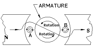
Figure 5-1: Torque Production in a DC Motor
a. Separately Excited DC Motor
The field (or stator) coil contains a relatively large number of turns which minimizes the current required to produce a strong stator field (Figure 5-2). It is connected to a separate DC power supply, thus making field current independent of load or armature current.
Excellent speed regulation is characteristic of this design which lends itself well to speed control by variation of the field current.
Separately excited DC motors can race to dangerously high speeds (theoretically infinity) if current to the field coil is lost. Because of this, applications should include some form of field current protection as an unprotected motor could literally fly apart.
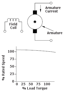
Figure 5-2: Separately Excited DC Motor
b. Series Field DC Motor
The field coil has a relatively small number of turns, and is connected in series with the armature (Figure 5-3). Because it carries full armature current, the magnetic field strength increases with load and armature current.
Very high starting torque is the characteristic of this design.
Speed regulation is poor with a very high no load speed.
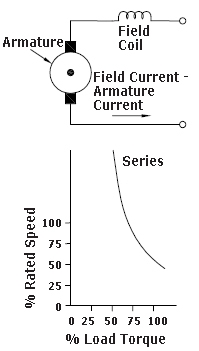
Figure 5-3: Series Field Motor
c. Compound DC Motor
The compound DC motor uses both series and shunt field windings, which are usually connected so that their fields add cumulatively (Figure 5-4).
This two winding connection produces characteristics intermediate to the shunt field and series field motors.
Speed regulation is better than that of the series field motor.
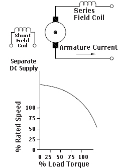
Figure 5-4: Compound DC Motor
d. Permanent Magnet DC Motors
These motors use permanent magnets in place of field windings to establish the stator magnetic field (Figure 5-5).
Permanent magnets provide constant field strength, with motor characteristics similar to that of the shunt field DC motor.
Permanent magnet motors are often used in low horsepower applications, particularly those that are battery operated (e.g. windshield wiper motor). However, with recent developments in magnet technology, permanent magnet motors can be greater than 200 HP.

Figure 5-5: Permanent Magnet DC Motor
Previous: AC Motors | Table of Contents | Next: Advanced Motors
Page details
- Date modified: