
Selection of VFD Drives
a. Electrical Considerations When Applying VFD to AC Motors
Successful application and maintenance of VFD drives requires an understanding of their impact on the motor and electrical distribution system.
The application of VFDs to induction motors can cause effects which must be considered for successful operation. Examples include:
- The ability of a motor to cool itself effectively is reduced as the motor is slowed down. Over-sizing the motor or providing external forced air ventilation may be required with extended operation at low speeds and high loads.
- Operation at different speeds can cause mechanical resonances in driven equipment. These speeds should be identified and programmed out of the motor’s operating range.
- VFDs generate harmonic voltages and currents which can, in some cases, cause undesirable effects on the electrical distribution system and affect equipment operation. If a power quality problem is suspected, the electrical system should be examined by a qualified person. Sometimes isolation transformers, line reactors or filtering devices will be required to minimize these effects. Contact your local electrical utility representative for more information. Installation of filtering devices should be considered at the time of purchase of VFDs to minimize power quality issues in the electrical system. A practitioner trained in this area should be used to evaluate and determine this requirement.
Electrical Supply to Drives
AC drives require an acceptable electrical supply for safe, successful and reliable operation.
Single phase drives have standardized voltages of 120 and 240 volts. Three phase motors have standardized voltages of 200, 230, 460 and 575 volts.
The nominal supply voltage of the distribution system is normally higher than the drive nameplate voltage to allow for voltage drops from the distribution transformer to the point of utilization.
Rated frequency is usually 60Hz (hertz or cycles per second) in North America.
Harmonics
Harmonic distortion of voltage and current is produced in electrical systems by non-linear loads such as VFDs, welders, rectifiers, Uninterruptible Power Supplies (UPS), arc furnaces etc. Harmonics cause electrical waveform distortion that can propagate through the entire power system and even outside of the plant. The source of harmonic distortion in VFDs is the solid-state power switching devices used to generate the varying supply frequencies.
These effects, known as “line harmonic currents”, are multiples of the fundamental 60 Hz supply current. For example, a frequency of 180 Hz is called the third harmonic. These currents generate harmonic voltage distortions which often exceed acceptable levels.
For more information, refer to the CEATI Power Quality Energy Efficiency Reference Guide.
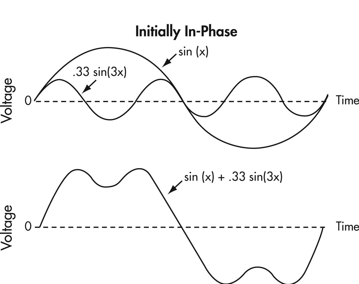
Figure 7: Harmonic Amplitudes
Text version Figure 7
Figure 7
Two graphs illustrating harmonic amplitudes. The two graphs each show two sin waves representing voltage vs. time, crossing over a middle dashed horizontal line.
In the first graph the larger sin wave is marked as sin(x) and the second sin wave is marked as .33 sin(3x). Sin wave sin(x) shows one cycle with one half of the wave above the horizontal line and one half below. Sin wave .33 sin(3x) shows three cycles in the same span as one cycle of sin wave sin(x), with three waves above the dashed line and three waves below the dashed line.
The second graph illustrates the formula sin(x) + .33 sin(3x). It shows one cycle of a double humped sin wave, with one half of the wave above the dashed line and one half below it.
The odd harmonic amplitudes usually decrease with increasing frequency, so the lowest order harmonics are the most significant. Even numbered harmonics are not normally generated by VFD drive systems.
Harmonics occur as long as the harmonic generating equipment is in operation and tend to be of a steady magnitude.
Harmonics may be greatly magnified by power factor correction capacitors. The supply system inductance can resonate with capacitors at certain harmonic frequencies developing large currents and voltages, which can damage equipment.
Effects of Harmonics
Microprocessors, numerically controlled machines, and process controllers all rely on accurate control signals. The presence of harmonics can cause these devices to malfunction. Harmonics can also cause interference with computers and improper operation of electronic equipment. They can also cause capacitor and fuse failure.
Motors run at higher temperatures in the presence of harmonic currents. Motors consume more energy as they have to overcome ‘counter rotating’ torques created by odd harmonics.
This may cause premature breakdown of insulating materials and a reduction in life. The motor will also drop in overall efficiency, experience voltage stresses on its windings and experience torque pulsations.
Dealing with Harmonics
If a harmonic problem is suspected, it should be confirmed before any attempt at corrective action is taken. A fairly simple test consists of viewing the power system waveforms on an oscilloscope. Significant waveform distortion is an indication of harmonic presence. Power harmonic analyzers can be used to measure the magnitude of the individual harmonics. This work is often best left to an expert in power quality services.
There are a variety of ways in which users can resolve these problems, after ensuring the installation meets the applicable electrical code including adequate grounding:
Separate Supply
Ideally, loads producing harmonics, and sensitive loads, should be supplied from entirely separate feeders and independent transformers.
Isolation Transformers and Line Reactors
Isolation transformers and line reactors are frequently used to protect the drive as well as the AC line from distortion.
Filters
Harmonic filters can be used to reduce the amplitude of one or more fixed frequency currents to prevent them from entering the rest of the system. Filters can be custom designed to suit the electrical environment.
Cable Length
Cable length should be kept as short as possible, i.e., less than 15 meters or 50 feet, wherever possible.
As a general rule of thumb, it is considered good practice to buy a complete drive system that includes line reactors rather than just purchasing the drive on its own. Generally a 3% to 5% impedance line reactor will prevent harmonics generated by a VFD from interfering with sensitive equipment on the distribution system.
If non-linear loads exceed 20% of the total plant load, special consideration should be given to performing a harmonic study and minimizing potential harmonic impact through the use of isolation transformers in addition to line reactors.
Specifying Drives for Harmonics
Drive specifications often cite “The power conditioning equipment shall not produce voltage distortion or notches in excess of the limits suggested in IEEE 519”, but it may be unclear what this means for a particular installation. What does meeting IEEE 519 mean when installing a drive on a power system?
IEEE’s Recommended Practices and Requirements for Harmonic Control in Electric Power Systems, IEEE Std 519-1992, is often referenced but may not be well understood.
IEEE 519-1992 contains sections on problems caused by harmonic currents and voltages, calculation examples, application examples, and the harmonic currents caused by different types of power converters and non-linear loads.
From a practical drive application point of view, meeting harmonic requirements for drives means having less than 5% total harmonic distortion of the current at the terminals of the drive at rated load. At low power demand with variable torque loads, the current’s total harmonic distortion (THD) may be higher than 5% as measured by a harmonic analyzer, but the magnitude of the harmonic current will be less than those produced at full load.
b. Motor Considerations
Motor Electrical Issues
Winding insulation systems are classified by their temperature or thermal capabilities. Tests used to prove thermal properties for low voltage systems do not stress the electrical insulation beyond 600 volts.
Application of a PWM VFD can cause voltage transients well above the rated voltage of the motor which can lead to failure of the insulation system in a very short period of time.
To understand this, consider the way in which a PWM inverter approximates a sinusoidal current waveform. The following figures show typical voltage and current waveforms for Pulse Width Modulation inverters.
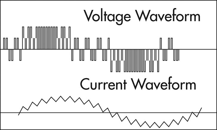
Figure 8: Voltage and Current Waveforms
Text version Figure 8
Figure 8
Two graphs illustrating voltage and current waveforms.
The first graph shows the voltage waveform and is made up of a series of pulses controlled by the inverter’s output devices. The width or duration of these pulses is controlled to approximate a sinusoidal current waveform. Each pulse appears as bar above or below the horizontal line representing the zero voltage point.
The second graph illustrates a current waveform, which appears as a saw tooth pattern that approximates a sin wave. The saw tooth pattern goes above and below the zero voltage horizontal line for one cycle.
The voltage waveform is made up of a series of pulses controlled by the inverter’s output devices. The width or duration of these pulses is controlled to approximate a sinusoidal current waveform. Figure 9 is a half cycle voltage waveform for a typical PWM inverter operating on a 600 volt system.
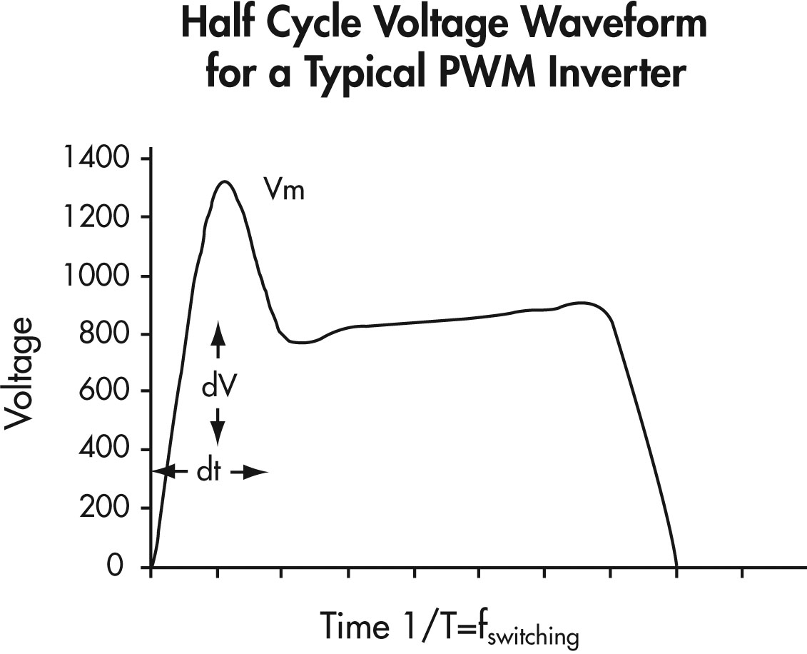
Figure 9: Half Cycle Voltage Waveform for a Typical PWM Inverter
Text version Figure 9
Figure 9
A graph showing voltage on the vertical axis and time on the horizontal axis.
The graph illustrates a half cycle voltage waveform which rises quickly in one time unit to a voltage of 1300 and drops in one time unit to a voltage of 800 and then rises more slowly to 900 in five more time units and then drops back down to zero in one more time unit.
The maximum voltage stress on the insulation system (Vm) can be significantly higher than the motor’s rated voltage and have extremely fast voltage rise times (shown in Figure 9).
Due to multiple reflections or resonance effects, the frequency can increase due to the interactions of the PWM switching frequency and waveshape, the cable length supplying the motor, and the inductance of the motor.
A voltage reflection of up to two times the applied voltage can occur due to standing waves or a “ringing effect”, and becomes more problematic with longer cable runs (typically greater than 15 m or 50 feet).
A “ringing effect” creates very high voltage stresses across the first few turns of the motor windings, and can result in interim short-circuits and ground wall insulation failure.
This problem can be minimized by using appropriate filtering, using motors with improved insulation systems (inverter duty motors) and ensuring that repaired motors have upgraded insulation systems.
Many VFDs provide for user adjustment of the switching frequency. This frequency can be adjusted over a range as broad as 500 Hz to 20 kHz. The choice of switching frequency can be significant because it defines the number of voltage overshoots occurring at the motor in a certain amount of time. Higher switching frequencies will result in higher numbers of overshoots and higher magnitudes, which will stress the motor’s insulation system. If the motor’s peak voltage rating is higher than the level of the overshoot, high switching frequency should not be a problem. If, however, the overshoot levels are higher than the peak voltage rating of the motor, the use of a lower switching frequency may reduce the overshoot levels below the peak voltage rating of the motor. However, too low a frequency may cause an audible noise from the motor which may be undesirable in some applications such as HVAC systems.
Factors to consider include:
- reducing cable runs where possible,
- using inverter output filter reactors (1%-3% impedance is typical),
- using a lower switching frequency,
- for new and repaired motors, using additional lacing on end turns, phase paper, VPI resin and pulse resistant magnet wire enamel (triple, quad or new heavy build),
- maintaining the original winding design when rewinding motors since reducing turns increases inter-turn voltage levels.
Motor Selection Issues
Thermal considerations of motor operation with a VFD should be one of the first areas of attention for successful application. As the motor speed is reduced, the amount of cooling available from the motor’s ventilation system is reduced, so motor torque must be limited at reduced speed to avoid overheating.
In addition to the reduced cooling capability, motors have additional internal heating due to the non-sinusoidal voltages and currents from the inverter operation.
The application of a VFD to a variable torque load such as a fan or centrifugal pump does not usually present problems, but constant torque or constant horsepower loads can cause motor overheating at reduced speeds because there is less air flow over the motor.
It should be noted that many applications where a DC motor has been replaced by an AC induction motor with an inverter are of the constant torque or constant horsepower class.
Figure 10 shows the allowable torque of NEMA design A&B motors due to reduced cooling from operating at reduced speeds. It can be used as a guide for de-rating motors or selecting an appropriately oversized motor.
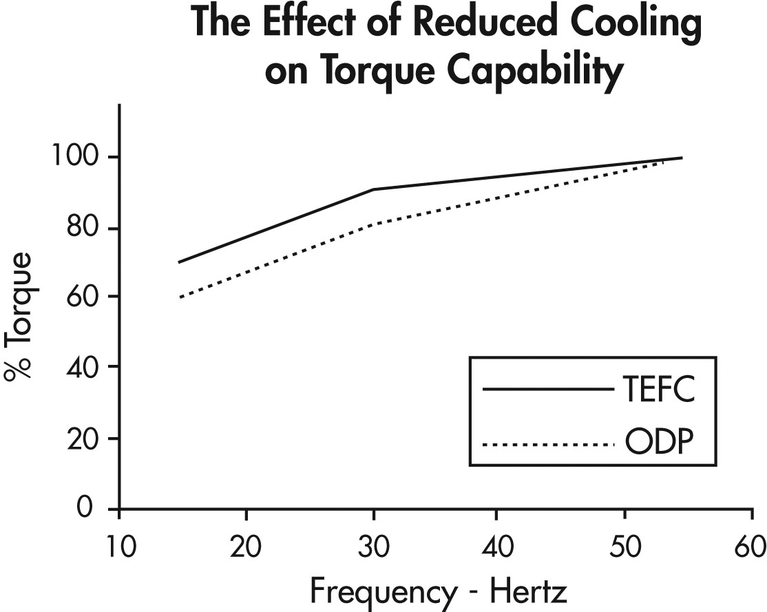
Figure 10: The Effect of Reduced Cooling on Torque Capability
Text version Figure 10
Figure 10
A graph showing per cent of torque on the vertical axis and frequency in hertz (hz) on the horizontal axis.
The graph shows two lines; a solid line marked as TEFC, and a dashed line marked as ODP.
Starting at 15 hz, the solid line is at 70% torque. It rises to 90% torque at 30 hz and then more gradually rises to 100% torque at 55 hz.
Starting at 15 hz, the dashed line is at 60% torque. It rises to 80% at 30 hz and then more gradually rises to 100% at 55 hz.
The use of a motor with a 1.15 service factor and class F insulation is generally recommended to allow for additional heating due to harmonics.
The ability of a motor to cool itself effectively is reduced as the motor is slowed down. Oversizing the motor or providing external forced air ventilation may be required with extended operation at low speeds and high loads.
“Inverter duty” motors are designed for optimized performance when operated with VFDs. These motors typically have better insulation systems and can also be forced ventilated with auxiliary blowers available as an option. This allows them to run cooler rather than having to oversize them when running high torque loads.
When applying a PWM inverter it is important to check for shaft currents on motors with frequent or unusual bearing failures. Shaft currents are not normally a problem with motors less than 20″ in core diameter, but can become a problem with high frequency harmonics associated with inverter use. Shaft voltages exceeding 0.3-0.5 volts may indicate potential trouble and may require shaft grounding or insulating the non-drive bearing.
Physical & Environmental Issues
VFDs must be selected to ensure that they have adequate protection from their environmental conditions.
VFDs are usually mounted into an electrical enclosure with other electrical devices, or as a standalone unit in its own enclosure.
The National Electrical Equipment Manufacturers Association (NEMA) has determined standard enclosure types to protect electrical equipment and to protect people from exposure to that equipment for standard environmental conditions. They are designated as follows:
| TYPE | NEMA ENCLOSURE |
|---|---|
| 1 |
General Purpose-indoor |
|
2 |
Drip proof-indoor |
|
3 |
Dust tight, Rain tight, Sleet tight-Outdoor |
|
3R |
Rain proof, Sleet Resistant-Outdoor |
|
3S |
Dust tight, Rain tight, Sleet proof-Outdoor |
|
4 |
Watertight, Dust tight, Sleet Resistant |
|
4X |
Watertight, Dust tight, Corrosion Resistant |
|
5 |
Dust tight-indoor |
|
6 |
Submersible, Water tight, Dust tight |
|
6P |
Watertight-Prolonged Submersion |
|
7 |
Class 1, Group A, B, C or D Hazardous Locations, Air-Break-Indoor |
|
8 |
Class 1, Group A, B, C or D Hazardous Locations, Oil-immersed-Indoor |
|
9 |
Class II, Group E, F, or G Hazardous Locations Air-Break-Indoor |
|
10 |
Bureau of Mines |
|
11 |
Corrosion-Resistant and Drip proof Oil-Immersed |
|
12 |
Industrial Use, Dust tight and Drip tight-Indoor |
|
12K |
Industrial Use, Dust tight and Drip tight with knockouts |
|
13 |
Oil tight and Dust tight-Indoor |
The following is a more detailed description for commonly used enclosure types:
- Type 1 — Enclosures constructed for indoor use to provide a degree of protection to personnel against access to hazardous parts and to provide a degree of protection for the equipment inside the enclosure against ingress of solid foreign objects (falling dirt).
- Type 2 — Enclosures constructed for indoor use to provide a degree of protection to personnel against access to hazardous parts, to provide a degree of protection of the equipment inside the enclosure against the ingress of solid foreign objects (falling dirt) and to provide a degree of protection with respect to harmful effects on the equipment due to the ingress of water (dripping and light splashing).
- Type 3 — Enclosures constructed for either indoor or outdoor use to provide a degree of protection to personnel against access to hazardous parts, to provide a degree of protection of the equipment inside the enclosure against ingress of solid foreign objects (falling dirt and windblown dust), to provide a degree of protection with respect to harmful effects on the equipment due to the ingress of water (rain, sleet, snow) and that will be undamaged by the external formation of ice on the enclosure.
- Type 4X — Enclosures constructed for either indoor or outdoor use to provide a degree of protection to personnel against access to hazardous parts, to provide a degree of protection of the equipment inside the enclosure against ingress of solid foreign objects (windblown dust), to provide a degree of protection with respect to harmful effects on the equipment due to the ingress of water (rain, sleet, snow, splashing water, and hose directed water), that provide an additional level of protection against corrosion and that will be undamaged by the external formation of ice on the enclosure.
In addition to protection from contamination and ingress of dirt, dust, water, etc., operation within the following limits would be considered usual operating conditions:
- Exposure to an ambient temperature in the range of 15°C to 40°C.
- Exposure to an altitude which does not exceed 3300 feet (1000 meters).
- Installation on a rigid mounting surface.
- Installation in areas or supplementary enclosures which do not seriously interfere with the ventilation of the drive.
Vibration and Resonance
There is a general assumption that slowing down rotating equipment leads to less wear and tear and hence promotes better maintenance conditions. Frequently, equipment life can be extended through the benefits of variable speed. However, there are a number of detrimental mechanical conditions that can arise when equipment is slowed down.
Most machines are designed to operate at a speed which is selected at a calculated safe margin below the first critical speed or natural frequency of the shaft.
In certain cases, to facilitate shaft design, some high speed machines are designed to operate between the first and second critical speeds. A speed reduction for a machine of this type could result in operation at the first critical speed.
For larger installations, contact should be made with the machine manufacturer to ensure that the critical speeds are known and dealt with appropriately.
Resolving vibration and resonance usually involves programming the VFD so that it will not operate equipment in the critical speed range.
If the design data cannot be located, field tests should be performed or the complete apparatus should be measured and the critical speeds recalculated.
Page details
- Date modified: